
Wire a Tiny House: A Beginner’s Guide
A tiny house may have fewer rooms than a conventional home, but that does not make its electrical system unimportant—or automatically simple. The same 120/240-volt electricity that powers a full-sized house may be running through the walls of a building that is only a few hundred square feet. A loose connection, undersized conductor, overloaded circuit or incorrect grounding arrangement can still cause a serious shock or fire. In fact, the compact nature of a tiny house can make good planning even more important because electrical equipment, plumbing, insulation, heating appliances and combustible materials are all packed into a limited space.
The good news is that a tiny-house electrical system is easier to understand when you break it into sections. Power enters the building, passes through a disconnect and electrical panel, and then travels along individual branch circuits to lights, receptacles and appliances. Once you understand that path—and the roles of hot, neutral and bonding conductors—the system stops looking like a mysterious collection of coloured wires. You can begin planning where power is needed, which appliances require dedicated circuits and how the electrical work fits into the overall construction sequence.
This guide explains the fundamentals of wiring a grid-connected tiny house using common Canadian terminology, with particular attention to Ontario. It is intended to help homeowners plan intelligently, communicate with electricians and understand what they see on a wiring diagram. It is not a substitute for the Ontario Electrical Safety Code, an electrical inspection or professional judgement on a real installation.
Quick Answer: Can You Wire Your Own Tiny House?
In Ontario, a homeowner may perform electrical work in their own home, but the work must comply with the Ontario Electrical Safety Code and the required notification must generally be filed with the Electrical Safety Authority before work begins. A homeowner cannot avoid licensing requirements by hiring an unlicensed friend, handyman or general contractor to complete the electrical work. When electrical work is being hired out, it must be performed by a Licensed Electrical Contractor.
A building permit and an electrical notification are also separate matters. Obtaining a building permit for the tiny house does not automatically authorize the electrical installation. Almost all electrical work in Ontario requires a separate notification, and an accepted installation can receive a Certificate of Acceptance that may be important for insurance, resale and future renovations.
Ontario’s current electrical requirements are found in the 2024 Ontario Electrical Safety Code, also known as the 29th edition, which took effect on May 1, 2025. It incorporates the Canadian Electrical Code with Ontario-specific amendments. Anyone undertaking DIY electrical work should obtain the current requirements rather than relying on an old wiring book, a decades-old diagram or advice copied from a different province or country.
The sensible beginner approach is to take responsibility for the layout, appliance schedule, circuit plan, box placement and overall construction coordination, while bringing in a Licensed Electrical Contractor for the service, panel, load calculations and any part of the system you are not fully qualified to complete. There is no shame in splitting the work intelligently. The objective is not to prove that you can touch every conductor yourself; it is to produce a safe, inspectable and dependable home.
First Decide What Kind of Tiny House You Are Wiring
Before buying cable or drawing receptacles on the floor plan, determine what the tiny house legally and functionally is. A permanent tiny house on a foundation, an accessory dwelling supplied from another building, a towable tiny house and an off-grid cabin may all use electricity, but they are not necessarily wired or approved in the same way.
A permanent tiny house receiving utility service may have a meter, service equipment, main disconnect and distribution panel similar to those in a conventional house. An accessory tiny house may instead be supplied by a feeder originating at the main building. A house on wheels may use an exterior shore-power inlet, while an off-grid house may depend on photovoltaic panels, batteries, a charge controller, an inverter and perhaps a generator.
Ontario notes that a structure on wheels can still be considered a building when it remains in one location and is connected to services such as electricity, water and sewage. Recreational vehicles and campers that are regularly towed may be treated differently, but simply installing wheels does not guarantee that a structure escapes building and zoning requirements. The intended use, servicing, anchoring and municipal rules all matter.
This article primarily describes a permanent dwelling with a conventional 120/240-volt alternating-current system. Shore-power, generator, battery and solar systems require additional equipment and design decisions. Those power sources must never be improvised or connected through a homemade backfeeding arrangement.
Understanding Volts, Amps and Watts
Electricity becomes much easier to plan when you understand three basic measurements: volts, amps and watts. They describe different parts of the same electrical relationship.
Voltage is often compared to pressure. It is the electrical potential that pushes current through a circuit. Most ordinary Canadian household receptacles and lighting circuits operate at a nominal 120 volts, while many larger appliances use 240 volts.
Amperage, or current, describes how much electrical charge is flowing. Circuit breakers, conductors, switches and receptacles all have current ratings. A circuit must be designed so that its conductors and devices can safely carry the expected current.
Wattage describes the rate at which electrical energy is being used. A small LED lamp might use fewer than 15 watts, while an electric heater or cooking appliance can use thousands of watts. The basic relationship is:
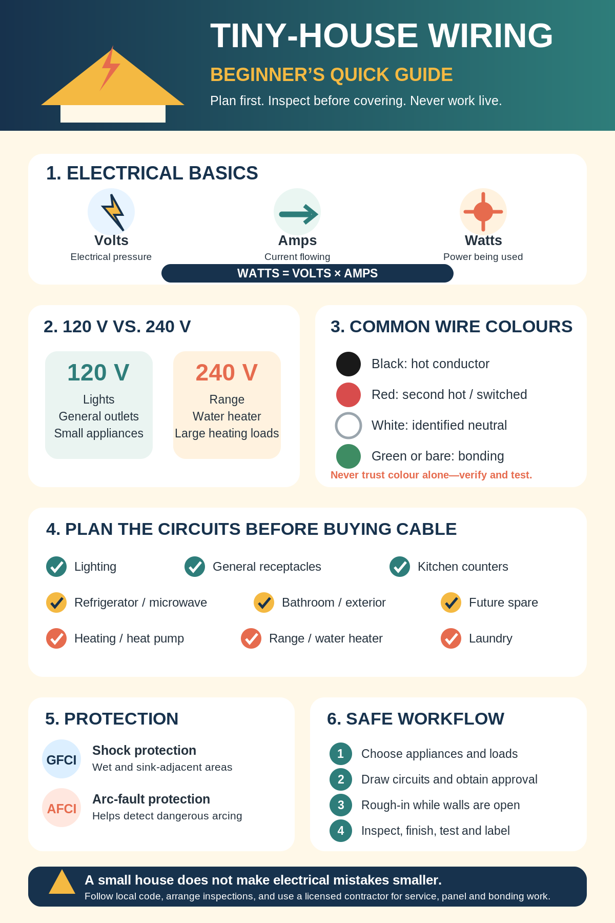
Watts = Volts × Amps
You can rearrange the formula to estimate current:
Amps = Watts ÷ Volts
For example, a 1,500-watt portable heater operating at 120 volts draws approximately 12.5 amps:
1,500 W ÷ 120 V = 12.5 A
That is a substantial portion of a typical 15-amp branch circuit. If the same circuit also supplies a kettle, toaster or hair dryer, the breaker may trip because the combined load is too high. This is why a physically small house can still require several circuits.
A 3,000-watt appliance operating at 240 volts also draws approximately 12.5 amps:
3,000 W ÷ 240 V = 12.5 A
Using 240 volts allows a large appliance to deliver more power without drawing as much current as it would at 120 volts. However, this simple calculation does not determine the required breaker or conductor size by itself. Appliance nameplate ratings, continuous-load rules, starting current, conductor type, installation conditions and manufacturer instructions must also be considered.
Why Modern Homes Use 120/240-Volt Power
People still commonly refer to “110-volt” and “220-volt” outlets, but the modern nominal residential voltages are 120 and 240 volts. A typical residential supply has two ungrounded conductors—often called hot legs—and a neutral conductor.
A load connected between either hot leg and neutral receives approximately 120 volts. A load connected between the two hot legs receives approximately 240 volts because the two legs are opposite each other in the electrical cycle. This arrangement allows one service to power both ordinary 120-volt devices and larger 240-volt equipment.
A standard 120-volt circuit normally uses:
- One hot conductor
- One neutral conductor
- One equipment bonding conductor
A straight 240-volt circuit may use:
- Two hot conductors
- One equipment bonding conductor
Some 240-volt appliances also require a neutral because they contain both 240-volt and 120-volt components. A modern range, for example, may use 240 volts for heating elements while using 120 volts for electronics, lights or controls. Those appliances require the conductor arrangement specified by the manufacturer and applicable code—not whatever cable happens to be available.
Plan the Appliances Before Planning the Panel
The most important tiny-house electrical decision often happens before a single wire is installed: choosing the appliances. Heating, water heating and cooking loads can completely change the required service, panel and circuit plan.
A tiny house using propane for space heating, water heating and cooking may have a relatively modest electrical demand. An all-electric tiny house with baseboard heaters, a tank water heater, range, clothes dryer, air conditioner and electric vehicle charger can have a substantial calculated load despite its small floor area. Square footage alone does not determine service size.
Create an appliance schedule containing the following information:
- Appliance or device name
- Manufacturer and model, when known
- Nominal voltage
- Rated wattage or amperage
- Plug-connected or permanently connected
- Manufacturer-recommended circuit
- Expected location
- Whether it may operate at the same time as other major loads
Include obvious appliances such as the refrigerator, range and water heater, but do not forget exhaust fans, well pumps, sump pumps, heat-trace cable, ventilation equipment, air conditioners, microwaves and exterior equipment. A bathroom fan may be small, but a tankless electric water heater can be enormous compared with the rest of the house.
The service and feeder must be selected using a proper residential load calculation rather than by simply adding breaker numbers or guessing that a 60-amp panel “looks big enough.” Ontario’s electrical guidance contains specific demand factors and calculation rules for dwelling services and feeders. The correct calculation accounts for the nature of the loads and which loads are likely to operate together.
A Practical Tiny-House Circuit Plan
Every project is different, but a tiny house commonly needs more branch circuits than a beginner initially expects. Combining everything onto two or three circuits may save a small amount of cable, but it can produce nuisance tripping, limit appliance choices and make future troubleshooting miserable.
A practical preliminary plan might include:
- General lighting circuit: Interior ceiling lights, wall lights and selected exhaust fans.
- Living and sleeping-area receptacle circuit: General-purpose receptacles for electronics, chargers, lamps and small devices.
- Kitchen counter circuit or circuits: Countertop appliances can draw significant current and must be planned according to current code requirements.
- Refrigerator circuit: Frequently assigned its own circuit so another appliance does not trip the refrigerator supply.
- Microwave circuit: Often dedicated, depending on its nameplate rating and installation instructions.
- Bathroom receptacle circuit: GFCI-protected and planned separately from lighting where appropriate.
- Water-heater circuit: Dedicated and sized for the exact unit.
- Heating or heat-pump circuit: Dedicated and based on the equipment nameplate and manufacturer’s minimum circuit requirements.
- Range or cooktop circuit: Usually 240 volts and sized for the selected cooking equipment. Ontario generally requires provision for an electric range receptacle in dwelling units, subject to specified exceptions.
- Exterior receptacle and lighting circuit: Using equipment and protection approved for the location.
- Laundry circuit: Required arrangements depend on whether the house contains a washer, separate dryer or combination appliance.
- Future-use circuit: Spare panel capacity for a workshop receptacle, air conditioner, solar equipment, generator connection or appliance upgrade.
This is a planning example, not an inspection-ready circuit schedule. The final design must consider the number of outlets, required receptacle locations, circuit loading, AFCI and GFCI protection, appliance instructions and local requirements.
Understanding the Breaker Panel
The electrical panel is the distribution centre of the tiny house. It receives power from the service or feeder and divides that power among the branch circuits. Each branch circuit is protected by a breaker selected for the conductor, equipment and intended load.
The main components include:
Main disconnect or main breaker: This allows the building’s electrical system to be disconnected from its source. Its rating is coordinated with the service or feeder supplying the panel.
Bus bars: Metal bars inside the panel distribute power to the branch breakers. A properly installed single-pole breaker connects to one hot leg, while a double-pole breaker connects to both legs.
Single-pole breakers: These generally supply 120-volt branch circuits such as lighting and ordinary receptacles.
Double-pole breakers: These generally supply 240-volt loads such as ranges, water heaters, electric heaters and some heat pumps.
Neutral bar: This is where circuit neutral conductors terminate. The neutral carries the normal return current of 120-volt loads.
Bonding bar: This connects equipment bonding conductors that help create a low-impedance fault path so protective devices can operate when metal equipment becomes energized.
Panel directory: Every breaker should be labelled clearly and specifically. “Kitchen counter east wall” is far more useful than “plugs,” and “bathroom receptacle” is better than “misc.”
Grounding and bonding are related but not interchangeable concepts. The exact location where the neutral is connected to the grounding and bonding system depends on whether the equipment is the main service equipment or a downstream panel. Incorrectly bonding the neutral again in a downstream panel can place normal current onto metal enclosures and bonding paths. Ontario guidance emphasizes single-point grounding arrangements in applicable service configurations, which is one reason panel and service work should not be treated as a beginner experiment.
Turning off a main breaker should not be treated as permission to explore the inside of service equipment. Conductors and terminals on the supply side may remain energized until the utility or other supply source disconnects them. Service conductors, meter equipment, grounding, bonding and connection authorization belong among the strongest “call a professional” points in the entire project.
How Breakers Protect the Wiring
A common misconception is that a breaker is installed primarily to protect whatever appliance is plugged into the circuit. Its central purpose is to protect the branch-circuit conductors and installation from excessive current.
If a conductor carries more current than it can safely handle, it can overheat inside the wall. The breaker is intended to open the circuit before that overheating damages the insulation or surrounding materials. Installing a larger breaker is therefore not a legitimate fix for a breaker that keeps tripping.
A tripping breaker may indicate:
- Too many loads on the circuit
- A short circuit
- A ground fault
- An arc fault
- Damaged equipment
- A loose connection
- Incorrect wiring
- A breaker or device problem
The proper response is to identify the cause. Replacing a 15-amp breaker with a 20-amp breaker without confirming the conductor and entire circuit are suitable can remove essential protection and create a fire hazard.
Breakers must also be specifically approved for the panel in which they are installed. A breaker that physically seems to fit is not automatically compatible. Follow the panel labelling and manufacturer’s approved breaker list.
Common Residential Cable Sizes
Canadian homes commonly use non-metallic-sheathed cable such as NMD90 in dry, protected interior locations. The cable type and conductor size must match the environment, circuit rating, installation method and code requirements.
Two common examples are:
- A 15-amp branch circuit using No. 14 AWG copper NMD90
- A 20-amp branch circuit using No. 12 AWG copper NMD90
ESA technical guidance uses these combinations in residential voltage-drop examples, but that does not make them universal instructions for every installation. Long runs, bundled conductors, high ambient temperatures, motor loads and other conditions can affect conductor selection.
Cable markings such as 14/2 and 14/3 describe the conductor gauge and the number of insulated conductors. A 14/2 cable generally contains two insulated No. 14 AWG conductors plus a bare bonding conductor. A 14/3 cable generally contains three insulated No. 14 AWG conductors plus a bonding conductor.
The additional insulated conductor in a three-conductor cable may be required for applications such as:
- Multi-wire branch circuits
- Three-way switch arrangements
- Appliances requiring two hots and a neutral
- Certain interconnected controls
- Some smoke-alarm arrangements
Never substitute cable solely because its outer jacket happens to be the colour you expected. ESA notes that the colour of non-metallic cable jackets is not mandated by the Ontario Electrical Safety Code; manufacturers may use colours to help distinguish products, but inspectors verify the actual conductor size.
Electrical Wire Colours Explained
Conductor colours communicate the intended function of a wire, but colours should never replace proper testing, tracing and documentation. Renovations, re-identification, previous errors and specialized circuits can produce exceptions.
In typical residential wiring:
Black: Commonly used as an ungrounded, current-carrying hot conductor.
Red: Commonly used as a second hot conductor, traveller, switched conductor or the second leg of a 240-volt circuit.
White: Generally used as the identified neutral conductor.
Bare copper or green: Generally used as an equipment bonding conductor, often informally called the ground wire.
Other colours may appear in controls, three-way switching, interconnected alarms, heating systems or larger installations. A white conductor may also be re-identified for another permitted use in specific wiring arrangements, but that must be done correctly and should never be assumed merely because an old installation appears to use it that way.
The bonding conductor normally does not carry current during ordinary operation. Its job is to connect exposed metal equipment and enclosures to the bonding system so that an electrical fault creates a strong return path capable of operating the protective device. A bonding conductor should never be used as a neutral.
Receptacles, Switches and Basic Connections
A standard 120-volt receptacle has terminals for the hot conductor, neutral conductor and equipment bond. Common receptacles use brass-coloured terminals for the hot side, silver-coloured terminals for the neutral side and a green screw for the bonding connection. Always follow the markings and instructions on the actual device rather than relying only on terminal colour.
The hot side of a standard polarized receptacle corresponds to the narrower blade slot. The neutral side corresponds to the wider slot. The round opening connects to the bonding system.
A basic single-pole light switch normally opens and closes the hot conductor feeding the light. It should not be used to switch the neutral while leaving the fixture energized. The bonding conductor connects to the switch’s bonding terminal and metal boxes are bonded where required.
More complicated switches may involve travellers, smart-switch neutrals, electronic controls or multi-location wiring. Do not assume that every wire inside a switch box serves the same function as it would in a basic single-pole installation. Read the device instructions and verify every conductor before disconnecting an existing arrangement.
For 240-volt equipment, both ungrounded conductors are energized. Some equipment requires no neutral, while other equipment requires two hots, a neutral and a bond. Never omit the neutral or repurpose a bonding conductor to serve as one.
What the Coloured Wire Connectors Mean
The little plastic caps used to join conductors are usually called twist-on wire connectors. “Wire-Nut” is a trademarked name that has also become a common generic term.
Connector colour does not identify whether the connection is hot, neutral or ground. It normally identifies a particular connector model, construction or approved wire range, and those meanings are not universal across every manufacturer. A red connector from one product family may accept different conductor combinations than a red connector from another.
Connector manufacturers publish specific approved conductor ranges. IDEAL, for example, offers twist-on connectors covering different combinations and gauges, from compact models intended for smaller branch-circuit conductors to larger connectors intended for heavier conductors. The connector must be selected from its listed wire-combination chart rather than by guessing from colour or physical size.
When making a splice:
- Use a connector approved for the conductor material, quantity and sizes.
- Strip the conductors to the length specified by the connector manufacturer.
- Follow the manufacturer’s instructions regarding pre-twisting.
- Ensure no bare current-carrying copper remains exposed below the connector skirt.
- Tug each conductor individually after completing the connection.
- Use connectors approved for damp, wet or underground locations where applicable.
- Keep every splice inside an approved, accessible electrical box or enclosure.
Ordinary electrical tape is not a substitute for an approved connector. Tape may be used for particular purposes, but wrapping a loose splice in tape does not turn it into a safe electrical connection.
Copper and aluminum conductors also require compatible devices, connectors and preparation methods. ESA notes that aluminum wiring can be safe when correct terminations and approved equipment are used, but problems frequently occur at improperly made connections. This is specialized work that should be handled by someone familiar with aluminum conductor requirements.
GFCI, AFCI and Tamper-Resistant Protection
Modern receptacles and breakers do more than provide overcurrent protection. Several safety features may be required depending on the circuit and location.
GFCI Protection
A ground-fault circuit interrupter monitors the current leaving and returning through a circuit. If it detects an imbalance indicating that current may be travelling along an unintended path—possibly through a person—it disconnects power rapidly.
In Ontario, receptacles within 1.5 metres of a sink require GFCI protection. GFCI protection is also used in other locations presenting increased shock risk, including specified outdoor and wet locations.
A GFCI receptacle has line and load terminals. Reversing or misusing these terminals can prevent the device or downstream protection from operating as intended. Follow the device instructions and test it using its built-in test button after installation.
AFCI Protection
An arc-fault circuit interrupter is designed to detect dangerous electrical arcing that may not draw enough current to trip an ordinary breaker. Damaged cords, loose connections and deteriorated wiring can produce arcing capable of igniting surrounding materials.
ESA states that AFCI protection is needed throughout much of a home, subject to specified exceptions. New dwelling circuits must be designed using the current rules rather than assuming AFCI protection is limited to bedrooms, as it was under older requirements.
Tamper-Resistant Receptacles
Tamper-resistant receptacles contain internal shutters intended to reduce the chance of a child inserting an object into one slot. New and replacement receptacles in dwelling units are subject to current tamper-resistant requirements. ESA specifically recommends them in homes with children and confirms that newly added receptacles must meet applicable TR requirements.
A circuit may require both arc-fault and ground-fault protection. This can sometimes be provided through a dual-function breaker or an approved combination of devices, depending on the panel and circuit arrangement.
Electrical Boxes and Cable Routing
Every switch, receptacle, splice and most fixture connections must be housed in a suitable box or enclosure. Boxes protect the connections from physical damage, contain sparks and keep live parts separated from combustible building materials.
Electrical boxes are not unlimited storage spaces for wire. Box-fill calculations account for conductors, internal clamps, devices and bonding conductors. Trying to force a deep GFCI receptacle, several splices and multiple cables into a shallow box can damage insulation and create loose connections.
Plan the box size before wiring. Tiny houses often use shallow walls, dense insulation and compact cabinetry, so a box that would fit easily in a standard wall may interfere with plumbing, exterior sheathing or interior finishes. Smart switches and GFCI devices also occupy more space than simple mechanical devices.
Cable routing should be planned alongside plumbing and structural framing. Cables must be supported, protected from sharp edges and kept away from locations where screws or nails are likely to penetrate them. Protective plates are used where conductors pass too close to the face of framing members.
Do not drill large holes indiscriminately through studs, joists or engineered lumber. Electrical convenience does not override structural requirements. Coordinate penetrations with the framing design and obtain approval before drilling engineered components.
Cable intended for dry indoor use should not be used outdoors, underground or in wet locations unless it is specifically approved for that environment. Underground feeders, exterior raceways and shore-power connections introduce moisture, burial-depth, mechanical-protection and corrosion requirements. ESA provides separate guidance for buried residential wiring because depth and protection depend on the wiring method and location.
Voltage Drop in a Remote Tiny House
The branch circuits inside a tiny house may be short, but the feeder supplying it may be long. A tiny home located 30, 50 or 100 metres from the main service can experience voltage drop if the feeder is not sized appropriately.
Voltage drop can cause:
- Dim or flickering lights
- Poor motor performance
- Slow heating
- Equipment malfunction
- Nuisance shutdowns
- Excessive conductor heating
- Reduced appliance life
The conductor may need to be larger than the minimum size normally associated with the breaker simply to maintain acceptable voltage at the far end. ESA publishes voltage-drop examples based on conductor size, circuit current and run length, demonstrating why long feeders require actual calculations rather than guesswork.
Do not purchase hundreds of dollars’ worth of underground cable until the service, load, distance, conductor material, burial method and voltage-drop calculation have been confirmed. An error here can be painfully expensive to correct.
Tools and Materials for Tiny-House Wiring
The exact materials depend on the approved design, but a grid-connected tiny house may require:
- Approved electrical panel with sufficient circuit spaces
- Main disconnect or service equipment
- Breakers specifically approved for the panel
- Correctly sized service, feeder and branch-circuit conductors
- NMD90 cable for appropriate dry interior locations
- Approved cable or raceway for exterior, underground or wet locations
- Electrical boxes with adequate fill capacity
- Tamper-resistant receptacles
- GFCI and AFCI protection
- Switches, dimmers and controls
- Lighting fixtures and fixture boxes
- Twist-on, push-in or lever-type connectors approved for the conductors
- Cable clamps, bushings, staples and supports
- Protective nail plates
- Bonding conductors and approved grounding equipment
- Weather-resistant exterior covers and devices
- Smoke and carbon-monoxide alarms as required
- Panel labels and circuit-directory materials
Useful tools may include:
- Insulated screwdrivers
- Linesman’s pliers
- Wire strippers
- Cable ripper
- Side cutters
- Utility knife
- Drill and appropriate bits
- Fish tape
- Torque screwdriver or torque wrench where specified
- Multimeter
- Approved voltage tester
- Plug-in receptacle tester
- Label maker
- Measuring tape and permanent marker
A non-contact voltage tester is useful as an initial indicator, but it should not be the sole method used to prove that equipment is de-energized. Test instruments must be understood, verified and used appropriately.
Electrical equipment used in Ontario must carry a recognized approval marking. Buying an inexpensive panel, inverter, receptacle or breaker online does not mean it is approved for installation in Canada. ESA publishes the certification marks and field-evaluation labels it recognizes.
A Sensible Tiny-House Wiring Sequence
1. Confirm the House Classification
Speak with the municipality and electrical authority before finalizing the construction design. Determine whether the structure is a permanent dwelling, accessory building, additional residential unit, modular building or recreational vehicle.
Ontario tiny homes generally must satisfy the same electrical safety requirements as regular homes. The province also recommends using a Licensed Electrical Contractor and confirms that building permits are required for tiny homes that fall under the Building Code.
2. Select the Appliances
Choose the range, water heater, heating system, ventilation equipment and other major loads. Obtain their installation manuals and nameplate requirements.
3. Complete the Load Calculation
Determine the required service or feeder capacity using the current code. Do not size the electrical service according to floor area alone.
4. Draw the Electrical Plan
Mark every receptacle, light, switch, alarm, appliance connection and exterior outlet on the floor plan. Assign each item to a preliminary circuit and identify which circuits require AFCI, GFCI or both.
5. Select the Panel and Breakers
Choose a panel with adequate amperage, approved breakers and room for future circuits. Filling every available breaker position on the first day leaves no practical expansion capacity.
6. Install Boxes and Plan Cable Routes
Install correctly sized boxes in accessible locations. Coordinate the routes with framing, plumbing, cabinetry, insulation and mechanical systems.
7. Run the Rough-In Wiring
Run, support and protect the cable according to the approved plan and applicable requirements. Leave the wiring visible for inspection and do not energize unfinished circuits.
8. Obtain the Rough-In Inspection
A rough-in inspection occurs after branch-circuit wiring and outlet boxes are installed but before they are concealed by insulation, vapour barrier or drywall. Depending on the project, other inspections may include trench and service or connection inspections.
9. Complete Insulation and Interior Finishes
Only cover the wiring after the required inspection stage has been completed and any deficiencies have been corrected.
10. Install Devices and Fixtures
Install approved receptacles, switches, fixtures and equipment according to their instructions. Use specified terminal torque values where provided and label every circuit accurately.
11. Complete Final Inspection and Testing
Test GFCI and AFCI devices, verify circuit operation and correct any deficiencies. Once the work has passed the required review, retain the Certificate of Acceptance with the house documents.
Common Tiny-House Wiring Mistakes
Assuming a Tiny House Needs Only a Tiny Panel
A small floor plan does not eliminate high-wattage appliances. Electric heat, water heating and cooking can create a sizeable load.
Designing Around Appliances That Have Not Been Selected
“Electric water heater” is not enough information. Different models can have dramatically different voltage, current and circuit requirements.
Using the Wrong Breaker
Breakers must match the panel and circuit. Physical fit alone does not establish approval or compatibility.
Oversizing a Breaker to Stop Nuisance Tripping
A breaker that trips is communicating a problem. Installing a larger breaker without verifying every part of the circuit can allow the conductor to overheat.
Treating Cable-Jacket Colour as a Code
Jacket colour may be a manufacturer convenience. Confirm the printed cable markings and conductor gauge.
Guessing Wire-Connector Capacity
Connector colour is not universal. Use the manufacturer’s approved conductor-combination chart.
Overfilling Boxes
Crowded boxes create damaged insulation, stressed devices and unreliable connections. Calculate box fill and use deeper or larger boxes where necessary.
Burying Junction Boxes
Splices must remain accessible in approved enclosures. Do not hide a junction behind drywall, fixed cabinetry or spray foam.
Forgetting Protective Plates
A cable routed close to the face of a stud can be penetrated later by a drywall screw, cabinet fastener or picture-hanging screw.
Bonding Neutral and Ground in the Wrong Place
An incorrect downstream neutral-to-bond connection can place current on metal components. The panel arrangement must reflect the actual service and feeder design.
Covering the Wiring Before Inspection
Rough-in wiring needs to remain visible for review. Installing insulation or drywall too soon can result in expensive removal.
Failing to Plan for Expansion
A spare raceway, several open breaker positions or a future equipment location can be inexpensive during construction and extremely valuable later.
Mixing Grid, Generator and Inverter Power Improperly
Multiple power sources require approved transfer, isolation and interconnection equipment. Never use a double-male “suicide cord” or any arrangement capable of backfeeding a utility system.
Special Considerations for Off-Grid Tiny Houses
An off-grid tiny house contains at least two different electrical worlds. Solar panels and batteries operate on direct current, while familiar household receptacles normally receive alternating current from an inverter.
A typical system may include:
- Solar modules
- Combiner equipment
- Charge controller
- Battery bank
- Battery overcurrent protection
- Battery disconnect
- Inverter or inverter-charger
- AC distribution panel
- Generator input
- Transfer equipment
- Grounding and bonding components
- Monitoring equipment
Battery systems can release tremendous fault current. Even a low-voltage battery bank can melt tools, ignite conductors or cause severe burns when short-circuited. Lithium-based energy-storage systems also introduce location, ventilation, temperature, fire and equipment-compatibility requirements.
Do not assume that an inverter’s neutral and grounding arrangement is the same in every operating mode. Inverter-chargers and transfer equipment may switch conductors internally, and the required bonding arrangement depends on the complete system. Use approved, compatible equipment designed as a system and have the design reviewed by someone qualified in energy-storage installations.
Special Considerations for Tiny Houses on Wheels
A towable tiny house may use an exterior power inlet similar to shore power on an RV. The inlet feeds a distribution panel through an appropriately protected cord and connection system.
The power available may be limited by the connection. A 30-amp, 120-volt supply does not provide the same capacity as a 50-amp, 120/240-volt supply, even though both may be casually described as “shore power.” Appliance choices must fit within the actual available power.
Flexible cords should not be treated as permanent substitutes for building wiring. Cord type, inlet rating, connector configuration, weather exposure, strain relief and overcurrent protection must all be coordinated.
A stationary tiny house on wheels connected to permanent services may still be treated as a building under Ontario rules. Confirm its status with the municipality and inspection authority before choosing an RV-style wiring approach.
When to Hire a Licensed Electrical Contractor
A careful homeowner may be able to understand much of a branch-circuit layout, but certain tasks carry unusually high consequences or require advanced code knowledge.
Bring in a Licensed Electrical Contractor for:
- Utility service and meter equipment
- Service-entrance conductors
- Main disconnect and panel installation
- Service and feeder load calculations
- Grounding and bonding design
- Long underground feeders
- Generator or transfer-switch installations
- Solar, inverter and battery-storage systems
- Electric heating and large appliance circuits
- Equipment with unclear nameplate requirements
- Aluminum conductors
- Troubleshooting unexplained tripping, heating or arcing
- Any work you cannot confidently explain and test
You should also stop when the physical installation does not match the plan. Finding unexpected conductors, shared neutrals, damaged insulation or unusual bonding arrangements is not a cue to improvise. It is a cue to document the condition and get qualified help.
Final Tiny-House Electrical Checklist
Before closing the walls, confirm that:
- The electrical notification has been filed.
- The latest approved plan is being followed.
- Every appliance has been accounted for.
- Service and feeder sizing are based on a load calculation.
- Breakers are approved for the panel.
- Conductors are correctly sized and identified.
- Cable is approved for its environment.
- Boxes are large enough and remain accessible.
- Cables are supported and protected from fasteners.
- GFCI, AFCI and tamper-resistant requirements have been addressed.
- Neutral and bonding conductors are properly separated or connected as required by the system design.
- Exterior equipment is approved for the location.
- No junctions will be hidden.
- The panel has a clear circuit directory.
- Rough-in inspection occurs before insulation and drywall.
- Final testing and inspection are completed before normal use.
- The Certificate of Acceptance is retained with the property records.
Conclusion
Learning how to wire a tiny house begins with understanding the complete system, not memorizing where three coloured wires attach to a receptacle. You need to know where the power comes from, how the service is sized, why circuits are divided, what breakers protect and how grounding, bonding, GFCI and AFCI protection work together.
The smaller footprint of a tiny house can make the layout easier to visualize, but it does not lower the electrical standard. Ontario’s tiny-home guidance specifically states that tiny homes must meet the same Electrical Safety Code requirements as regular homes.
Approach the project as a planned construction system. Choose the appliances first, complete a proper load calculation, draw every circuit, file the required notification, keep the rough-in visible for inspection and bring in a Licensed Electrical Contractor where the risk or complexity exceeds your abilities.
A successful DIY project is not one in which the homeowner refuses all professional help. It is one in which the finished home is safe, compliant, well documented and easy to maintain. When electricity is involved, knowing where to stop is every bit as important as knowing how to begin.
- Electrical Safety Authority: DIY Electrical Work — Learn about Ontario homeowner responsibilities, electrical notifications, inspections and legal hiring requirements.
- Government of Ontario: Build or Buy a Tiny Home — Review Ontario guidance covering tiny-home planning, building permits, zoning and Building Code requirements.