
Tiny House Electrical Wiring 101: A Beginner’s Guide to Circuits, Wires, Breakers and Panels
Electrical wiring has a strange reputation in the DIY world. From a distance, it can look almost ridiculously simple: run some cable, connect a black wire here, a white wire there, screw on one of those little colored plastic caps, install a breaker and turn everything on. Then you actually open a junction box or look inside an electrical panel and realize there is an entire organized system hiding behind those few wires.
That is especially true when wiring a tiny house. Because the building is small, it is tempting to assume the electrical system must be simple as well. In reality, a tiny home may contain a refrigerator, microwave, induction cooktop, water heater, heating and cooling equipment, lighting, bathroom receptacles, exterior receptacles, computers and perhaps even solar panels and batteries—all packed into a fraction of the space of a conventional house.
The good news is that residential electrical wiring is not mysterious once you understand the basic principles. Electricity follows predictable rules, and most residential wiring systems are built from the same handful of concepts repeated throughout the house. The challenge is that mistakes can cause fire, serious injury or electrocution, which makes electrical work very different from learning how to hang drywall or build a shelf.
This guide is therefore meant to provide electrical literacy, not turn a beginner into an electrician after one article. We will look at voltage, amperage, wattage, wire colors, grounding, electrical panels, circuit breakers, receptacles, switches, wire connectors and how a tiny-house electrical system can be planned. If you are considering doing your own electrical work, this should help you understand what you need to learn before you begin.
Electrical codes, homeowner-work rules, permits and inspections vary depending on where you live and what kind of structure you are building. Always verify the requirements for your jurisdiction before performing electrical work, and leave work involving energized service equipment or anything beyond your training and legal authority to a qualified electrician.
Start With the Big Picture: How Electricity Gets Through a House
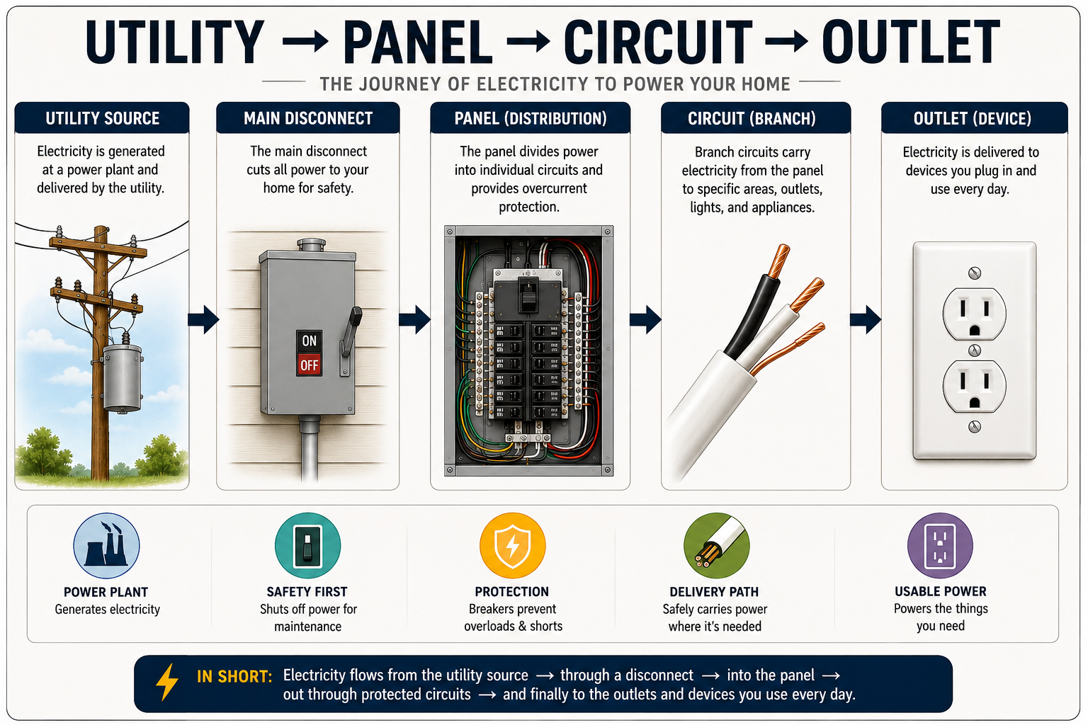
Before worrying about individual wires, it helps to understand what the entire electrical system is trying to accomplish. Electrical power enters the building from a source, reaches distribution equipment such as an electrical panel, and is then divided into separate circuits that carry electricity to lights, receptacles and equipment throughout the structure.
In a conventional home, the source may be the electrical utility. A tiny house might instead receive power from a shore-power connection, generator, solar-and-battery system or some combination of sources. The details differ considerably depending on the installation, but the basic principle remains the same: electricity has to enter the system, be controlled and protected, and then be safely distributed to the loads that need it.
The electrical panel is essentially the traffic controller for this process. Rather than running one giant circuit around the entire building, the panel divides the electrical system into multiple branch circuits. Each branch circuit has wiring and overcurrent protection selected for the loads it is expected to serve.
One circuit might power some general receptacles. Another could serve lighting. Other circuits might be dedicated to significant loads such as an electric water heater, heating equipment, cooking appliance or air conditioner.
Once you understand that hierarchy—power source, distribution panel, breakers, branch circuits and loads—residential wiring starts becoming much easier to visualize.
Voltage, Amperage and Wattage Without the Textbook Headache
Three electrical terms appear almost immediately whenever you start learning about wiring: voltage, amperage and wattage. They describe different characteristics of electricity, and understanding the relationship between them is one of the most useful things a homeowner can learn.
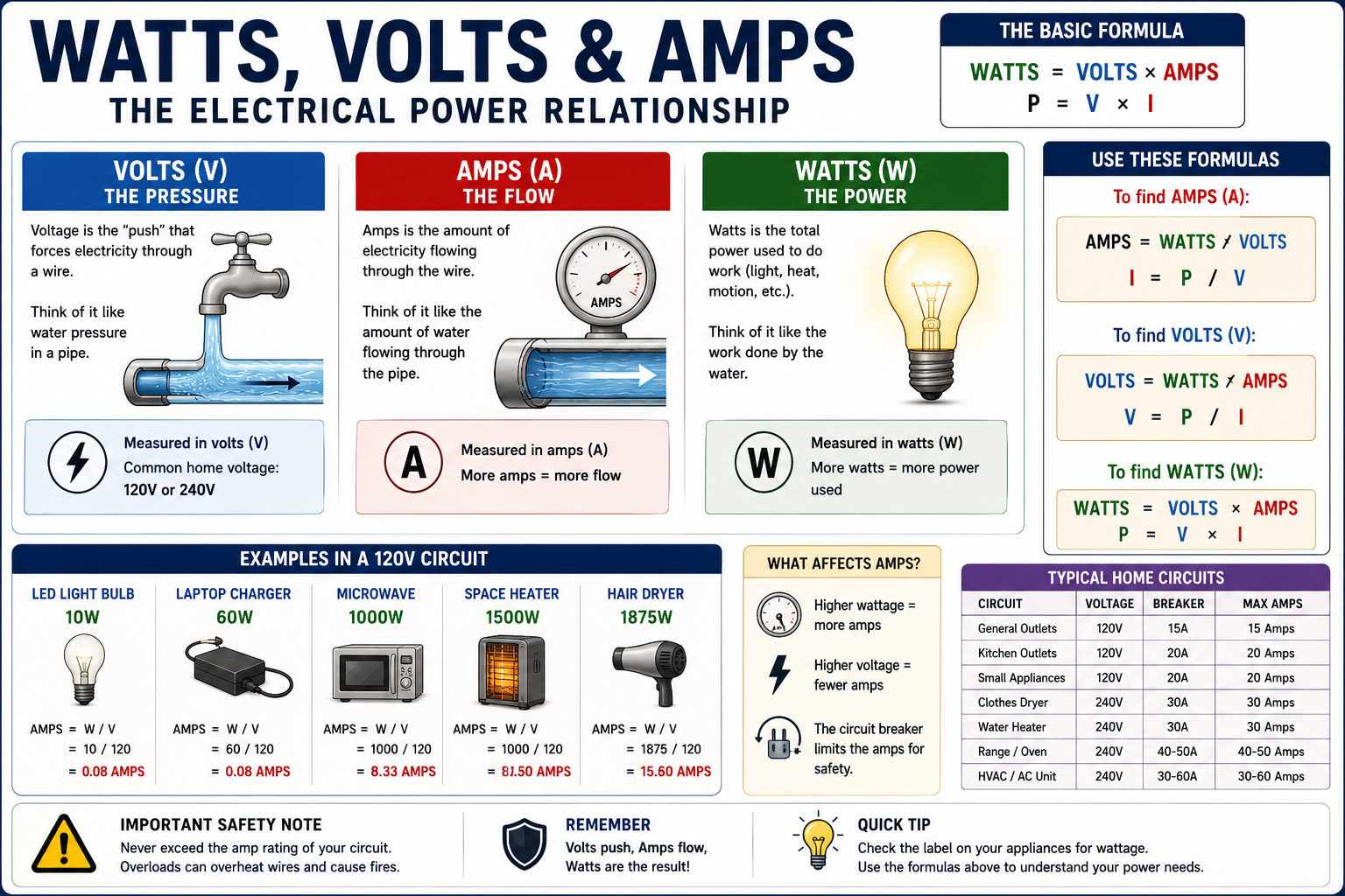
A common analogy compares electricity to water moving through a pipe. Voltage is somewhat like the pressure pushing the water. Current, measured in amperes or amps, represents the amount of electrical current flowing through the circuit. Wattage describes electrical power—the rate at which energy is being used.
The basic relationship is:
Watts = Volts × Amps
That simple equation becomes surprisingly useful in the real world. Suppose an electric heater is rated at 1,500 watts and operates on approximately 120 volts. Dividing 1,500 by 120 tells us that the heater draws about 12.5 amps under its rated operating conditions.
Now imagine plugging that heater into the same branch circuit as a microwave, toaster and coffee maker. Each appliance may individually work perfectly well from an ordinary receptacle, but together they can place a substantial demand on the circuit.
That is why electrical design is about more than asking whether an appliance’s plug physically fits into an outlet.
What Does 120 Volts and 240 Volts Mean?
In a typical North American residential system, many familiar lights and receptacles operate on nominal 120-volt circuits. Larger electrical loads may use 240 volts. Depending on the equipment, these might include electric water heaters, ranges, dryers, heating systems or other high-demand appliances.
The power equation helps explain one reason higher voltage is useful. If you want to deliver the same wattage at a higher voltage, less current is required. That does not make higher-voltage circuits casual DIY work; it simply explains part of the electrical engineering behind why different appliances use different supply arrangements.
A tiny house can still have surprisingly substantial electrical requirements. Reducing the square footage dramatically reduces certain loads such as lighting, but an induction cooktop, water heater and heat pump do not necessarily consume one-tenth as much electricity merely because the house is one-tenth the size of a large home.
That is why electrical service requirements should come from a proper load calculation rather than the assumption that “tiny house” automatically means “tiny electrical system.”
What Exactly Is a Circuit?
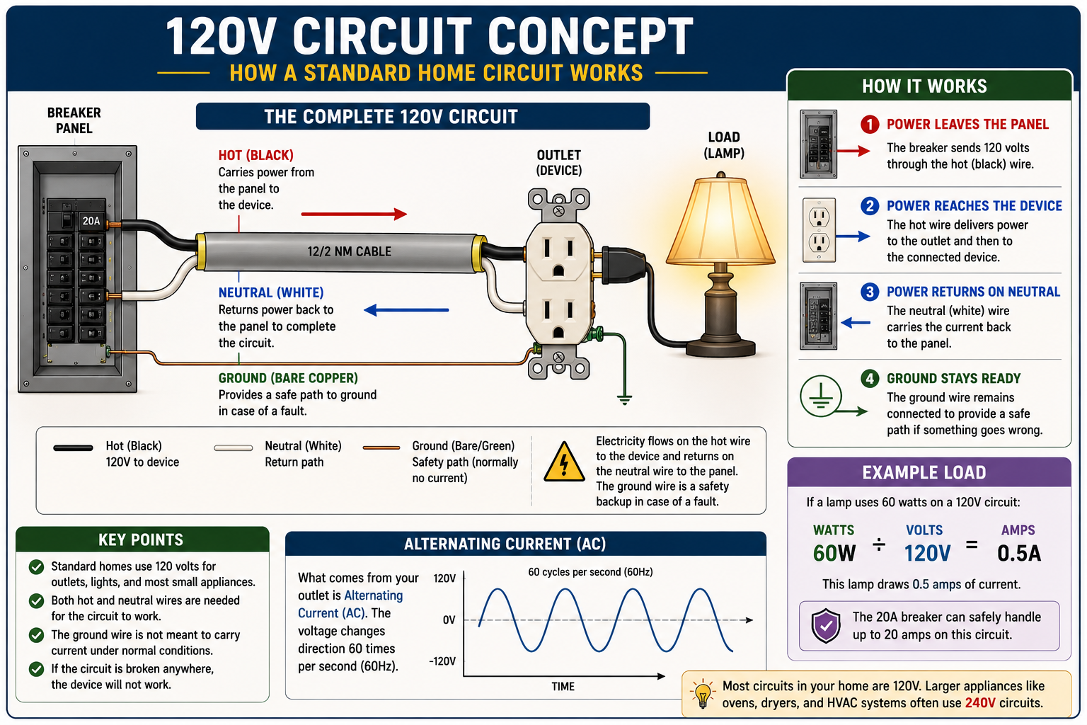
A circuit is a complete electrical path. In simplified terms, electrical current leaves the source through an energized conductor, travels through the load and returns through the intended circuit path. If that pathway is interrupted, the circuit stops operating.
A light switch demonstrates the idea beautifully. When the switch is open, the electrical path controlling the light is interrupted and the light is off. When the switch closes the appropriate path, current can flow through the load and the light operates.
Residential buildings contain many individual circuits rather than one enormous circuit. This allows each circuit to be designed and protected according to the loads it serves.
It also means a problem with one circuit does not necessarily shut down the entire building. A breaker can interrupt one branch circuit while the other circuits remain energized.
Hot, Neutral and Ground: The Three Conductors Beginners Need to Understand
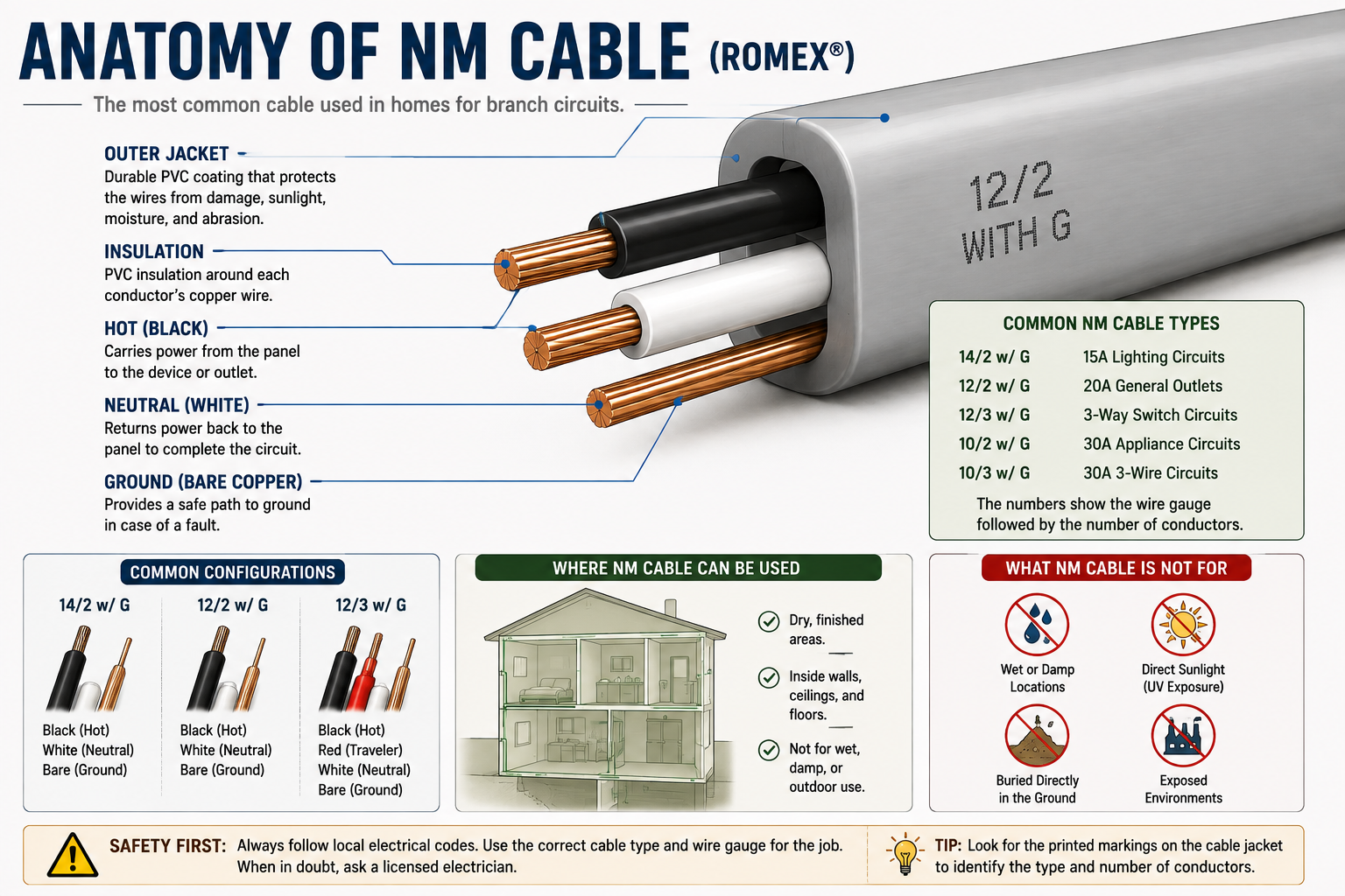
When someone first opens a residential electrical box, they may see black wires, white wires and bare copper or green wires. It is easy to assume these are simply three different versions of the same wire. They are not.
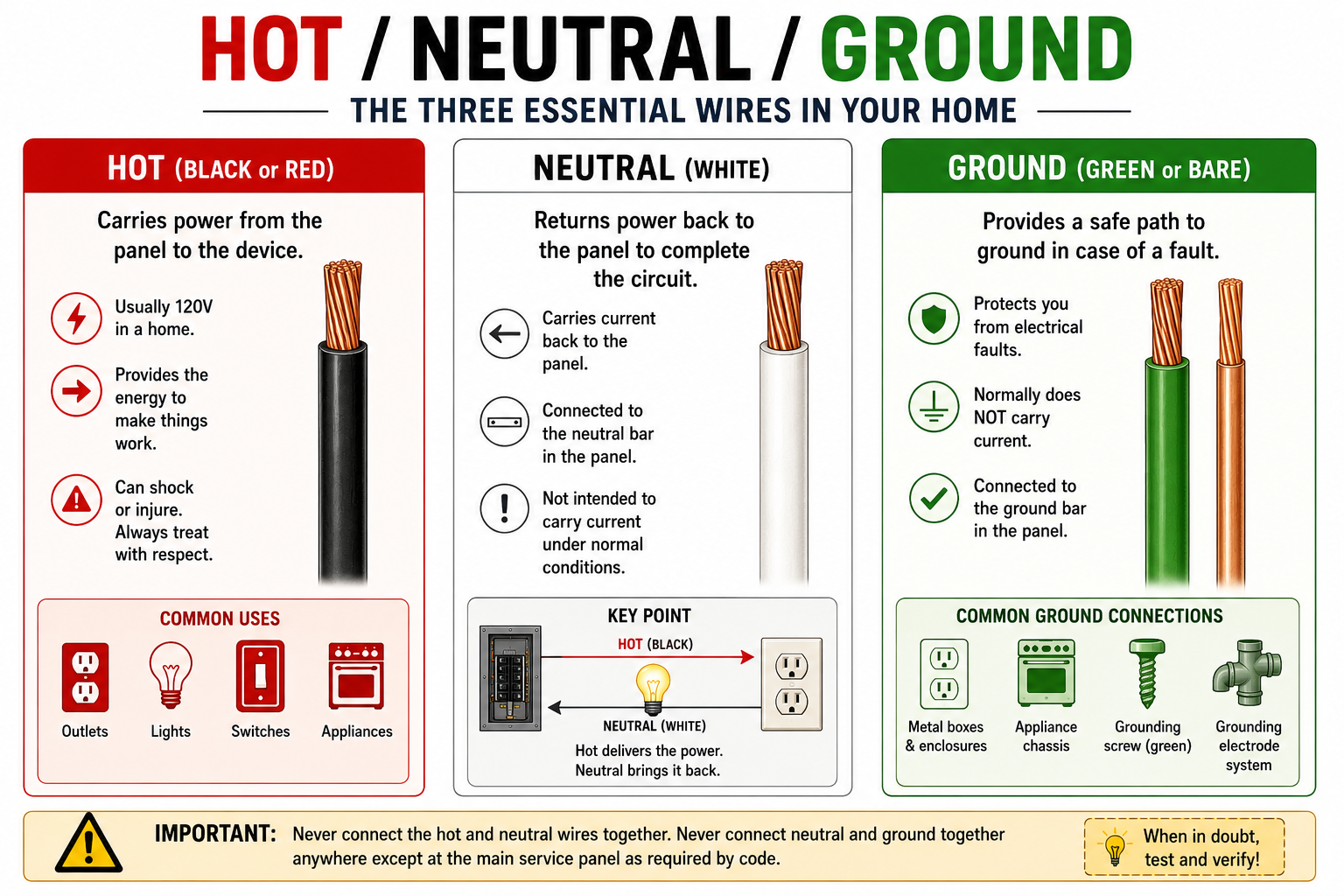
The hot, or ungrounded, conductor normally carries electrical energy from the source toward the load. In common North American residential wiring, black is frequently used as a hot conductor. Red and other colors may also appear as energized conductors depending on the circuit.
The neutral, or grounded circuit conductor, normally forms part of the intended return path for current in many 120-volt circuits. White is commonly associated with neutral conductors in residential wiring. However, real buildings contain different configurations, older wiring, permitted re-identification practices and sometimes incorrect previous work, so color alone should never be treated as proof that a conductor is safe.
The equipment grounding conductor serves a different purpose. It is commonly bare copper or green and normally should not be carrying the ordinary operating current of the load. Instead, it provides part of a low-impedance fault-current path so protective equipment can operate if something goes wrong and conductive metal parts become energized.
This distinction is extremely important because beginners sometimes conclude that neutral and ground are basically interchangeable. They are not.
Why Neutral and Ground Are Not the Same Thing
Neutral and ground are related within an electrical system, which is probably why they cause so much confusion. At designated locations within certain electrical systems, grounded and grounding conductors are intentionally connected or bonded according to the applicable electrical design and code. That does not mean they should be connected together everywhere.
Under normal operation, the neutral can carry return current from a load. The equipment grounding conductor normally should not be carrying ordinary load current. Its job is primarily related to fault protection and bonding conductive parts together safely.
If neutral and ground are improperly connected downstream in the electrical system, normal return current can end up flowing through metal components and grounding paths that were never intended to carry it continuously. That can create shock hazards and other dangerous conditions.
This is one reason grounding and bonding are among the subjects that deserve substantially more study before someone attempts panel work.
Do Wire Colors Always Tell You What the Wire Does?
Wire colors are incredibly useful, but they are not a substitute for understanding and testing the circuit. A black conductor is commonly hot, white is commonly neutral, and green or bare copper is commonly associated with equipment grounding in modern North American residential wiring. Those conventions help electricians and inspectors identify circuits efficiently.
But buildings change. Wiring may have been installed decades ago, renovated several times or altered by someone who did not follow proper practices. Certain circuit configurations can also use conductors in ways a beginner may not expect.
That means you should never assume that a wire is safe simply because it is white or that a conductor cannot be energized because its color seems wrong. Proper electrical work requires identifying the circuit, de-energizing it correctly and verifying the condition with appropriate test equipment and procedures.
Think of wire colors as labels that help tell the story. They are not magical protection against somebody having written the story incorrectly.
What Are Those Red, Yellow, Blue and Orange Plastic Caps?
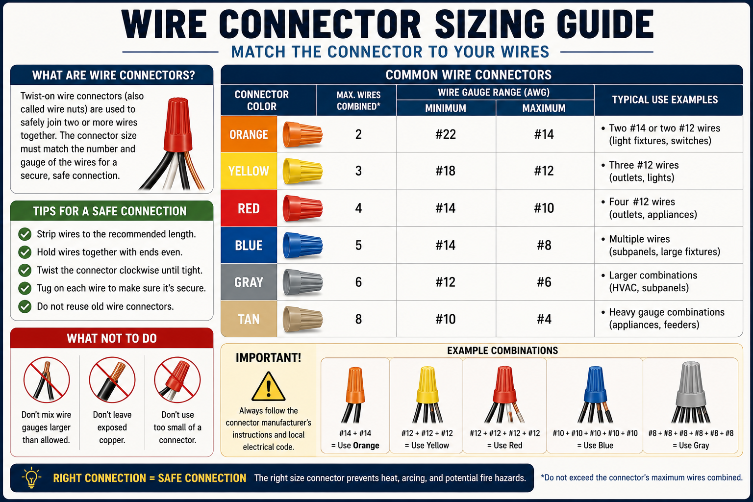
If you have ever looked inside an electrical junction box, you have almost certainly seen small cone-shaped plastic connectors twisted onto groups of wires. People commonly call them wire nuts, although the more general term is twist-on wire connectors.
They are designed to create an insulated electrical connection between compatible conductors when installed according to the connector manufacturer’s specifications. They come in numerous shapes, sizes and colors, and this is where a common misconception appears.
A red wire connector does not automatically mean it is for red wires or hot wires. A blue connector is not necessarily intended for blue conductors, and you should not assume that every green connector has exactly the same approved use simply because of its color.
Connector colors are generally part of a manufacturer’s product identification and sizing system. Different models accept different combinations of conductor sizes, quantities and sometimes materials.
For example, one connector may be approved for a particular combination of two conductors while a larger connector might accommodate several conductors within a specified gauge range. The correct answer is therefore not “use the yellow connector when you have three wires.” The correct answer is to check the conductor-combination information supplied by the manufacturer for that exact connector.
That may sound overly cautious for such a tiny part, but electrical connections matter enormously. A poor splice can develop resistance, resistance produces heat, and a failing connection hidden in a box can become a serious hazard.
What About Lever Connectors and Push-In Connectors?
Traditional twist-on connectors are not the only way conductors can be joined. You may also encounter lever-style connectors, push-in connectors and other listed splicing devices. These can be convenient, especially when multiple conductors must be joined in a crowded box.
The same basic rule applies to all of them. A connector should only be used with the conductor materials, gauges, quantities and installation methods for which that particular connector is approved.
A connector being physically able to accept a wire does not necessarily mean the combination is correct. Manufacturers publish specifications precisely because the internal connection must provide reliable electrical and mechanical contact.
Electrical work becomes considerably safer when you stop thinking in terms of “this looks like it fits” and start thinking in terms of “is this exact combination listed and approved?”
Understanding Wire Gauge
Electrical conductors come in different sizes. In North America, conductor size is commonly expressed using American Wire Gauge, or AWG.
One thing that initially feels backward is that smaller AWG numbers generally represent larger conductors. A 10 AWG conductor is larger than a 12 AWG conductor, which is larger than a 14 AWG conductor.
Why does the size matter? Because conductors have limitations on how much current they can safely carry under specified installation conditions. If too much current passes through a conductor, excessive heating can occur.
This is where online wiring advice can become dangerously oversimplified. You will often see quick charts assigning a certain wire gauge to a certain breaker size. Those charts can be useful for understanding the general concept, but actual conductor ampacity can depend on conductor material, cable type, insulation temperature rating, equipment termination ratings, ambient temperature, bundling, installation method and applicable electrical-code rules.
The important beginner principle is that conductor size, circuit protection, equipment ratings and electrical load all have to work together as one system.
Why You Should Never “Just Install a Bigger Breaker”
Suppose a breaker keeps tripping whenever several appliances are operating. A tempting solution might be to replace that breaker with a higher-amperage model so it stops shutting off.
That can be an extremely dangerous idea.
A circuit breaker is selected as part of a system that includes the conductors and connected equipment. If the circuit wiring is only suitable for the original circuit design, increasing the breaker rating could allow more current to flow through the conductors than they are intended to handle before the breaker trips.
The proper question when a breaker repeatedly trips is not, “How do I make the breaker stop tripping?” It is, “Why is enough current flowing to cause the breaker to operate?”
Sometimes the breaker is doing exactly what it is supposed to do.
What Does a Circuit Breaker Actually Protect?
People often think a circuit breaker exists mainly to protect whatever appliance is plugged into the wall. Its broader job is to protect the electrical circuit from dangerous overcurrent conditions.
If the current rises sufficiently beyond what the circuit is designed to carry, the breaker is intended to interrupt the circuit according to its operating characteristics. This helps prevent conductors and equipment from being subjected to unsafe levels of current indefinitely.
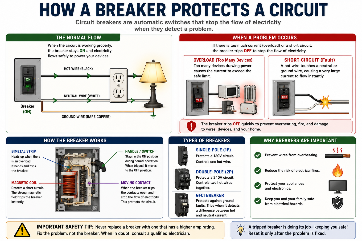
Breakers can trip for different reasons, including overloads and short circuits. Modern electrical systems may also use specialized protective devices that provide ground-fault or arc-fault protection.
This is another reason electrical panels contain more than a row of identical switches. Different circuits may require different forms of protection depending on their location, purpose and applicable electrical code.
Inside the Breaker Panel
The electrical panel is one of the most interesting components to understand conceptually—and one of the places where beginners need to be especially cautious physically.
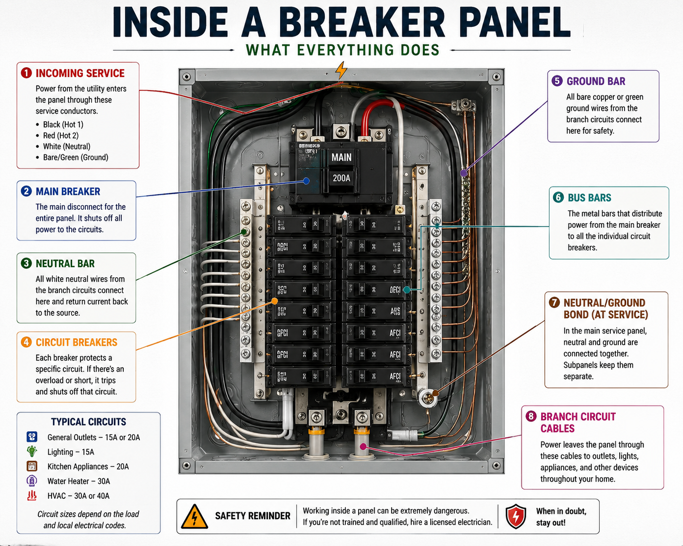
A typical distribution panel contains circuit breakers connected to energized bus structures, termination points for neutral and grounding conductors and conductors supplying the panel. Depending on the system, it may also contain a main breaker or other disconnecting equipment.
Each branch-circuit breaker distributes power to an individual circuit. The hot conductor for that branch circuit is connected through the appropriate breaker, while neutral and equipment grounding conductors terminate in locations dictated by the equipment design and the panel’s role within the electrical system.
Grounding and bonding rules become particularly important here. A service panel and a downstream distribution panel are not necessarily treated identically, and simply copying the arrangement you saw in another panel can be a serious mistake.
Most importantly, switching off the main breaker does not necessarily mean every component inside a panel is de-energized. In some configurations, incoming supply-side conductors and terminals can remain energized even when the main breaker is off.
That fact alone is a good reason to treat panel and service work as a significant dividing line between understanding residential wiring and casually experimenting with it.
Main Panel, Subpanel and Disconnects
You will frequently hear people use terms such as main panel, service panel, subpanel and disconnect. They are related pieces of the electrical-distribution system, but they do not necessarily perform exactly the same role.
The equipment at the electrical service has grounding and bonding requirements associated with its position in the system. A downstream panel supplied from another panel may require the neutral and equipment grounding paths to be handled differently.
Tiny houses make this especially interesting because there are several ways they can receive electrical power. A permanently installed tiny home might have electrical service arranged similarly to a conventional house, while a tiny house on wheels might connect to an external electrical supply.
Those different configurations can change how disconnects, grounding, bonding and overcurrent protection are handled. This is why identifying exactly what kind of tiny house you are building should happen before designing the electrical system.
What Is a Branch Circuit?
Once electricity reaches the distribution panel, individual breakers feed branch circuits throughout the building. These are the circuits that ultimately serve lights, outlets and equipment.
A tiny house might have separate circuits serving general receptacles, lighting, kitchen loads, bathroom loads, heating equipment, cooling equipment, water heating and other appliances. Exactly how these circuits must be arranged depends on the electrical code and the equipment being installed.
The goal is not to see how few breakers you can possibly use. Good electrical planning considers how people will actually live in the building.
Imagine having your coffee maker, microwave and portable heater all on the same heavily loaded circuit. Even if the wiring arrangement technically existed, the occupants might constantly trip the breaker during normal daily use.
A thoughtful electrical layout avoids unnecessary inconvenience while also satisfying safety and code requirements.
Dedicated Circuits
Some appliances and equipment need or are commonly provided with their own branch circuits depending on their characteristics and applicable code requirements. These are generally referred to as dedicated circuits.
The logic is straightforward. A substantial load can consume enough of a circuit’s capacity that sharing it with multiple other devices becomes impractical or unacceptable.
Examples in a tiny house might include certain heating equipment, water heaters, cooking appliances, air-conditioning systems or other large loads. The manufacturer’s electrical specifications are extremely important when planning these circuits.
This is one reason it makes sense to choose major appliances before completing the electrical design. You cannot accurately plan the building’s electrical needs if you do not know what the equipment requires.
Receptacles: Brass, Silver and Green
A common North American grounding receptacle gives us one of the clearest visual demonstrations of hot, neutral and ground connections.
Typical devices use brass-colored terminals for the hot side, silver-colored terminals for the neutral side and a green terminal for the equipment grounding connection. You should still follow the instructions supplied with the exact device being installed rather than assuming every electrical device is identical.
This is where the phrase “black to brass, white to silver” comes from. It can be a useful memory aid in the correct context, but it should not substitute for understanding the circuit.
Special devices such as GFCI receptacles may also have terminals marked LINE and LOAD. Those markings matter. Connecting conductors to the wrong terminals can change how the device operates and what downstream equipment receives protection.
The deeper lesson is that you should understand what each terminal does, not simply memorize which color normally goes beside it.
How Does a Light Switch Work?
A basic light switch is actually one of the simplest electrical concepts in a house. It opens or closes the electrical path controlling the load.
When the switch opens the circuit, current can no longer follow the intended path through the light and the light turns off. Close the circuit again and the light operates.
From there, switching becomes considerably more complicated. Three-way and four-way switching allow lights to be controlled from multiple locations. Dimmers contain electronics, and smart switches may require additional conductors such as a neutral connection.
That is why somebody replacing an old mechanical switch with a smart device can suddenly discover that the wiring in the wall does not match the new device’s requirements. The original switch may have needed nothing more than the conductors necessary to interrupt the controlled circuit, while the electronic switch itself may need continuous operating power.
What Is a Junction Box?
Electrical connections are not supposed to be casually joined together and buried inside a wall. Approved boxes and enclosures provide physical protection, contain electrical connections and help keep devices and splices accessible where required.
A junction box may contain conductors entering from several directions, splices made with approved connectors and sometimes a device such as a receptacle or switch. Boxes also need to be properly sized for what they contain.
This introduces the concept of box fill. You cannot simply keep stuffing wires and connectors into the smallest available box until the cover finally fits.
Conductors, internal clamps, equipment grounding conductors and devices can all affect box-fill calculations under the applicable rules. Planning larger boxes where several cables or devices meet can make an installation substantially easier to work with.
Accessibility matters too. Hiding a junction box permanently behind drywall creates an entirely different situation from installing a box with an accessible cover.
Overloads, Short Circuits and Ground Faults
These three electrical problems are often lumped together in everyday conversation, but they describe different conditions.
An overload occurs when a circuit is asked to carry more current than it is intended to carry under the circumstances. Running too many substantial loads simultaneously on one branch circuit is a common example.
A short circuit involves an unintended low-impedance connection between points at different electrical potentials. This can create very high fault current and cause protective equipment to operate rapidly.
A ground fault occurs when electrical current takes an unintended path involving ground or grounded conductive parts. A person can potentially become part of a fault-current path, which is one reason specialized ground-fault protection exists.
Knowing the difference helps explain why modern electrical systems use several different forms of protection instead of relying on one simple breaker to address every possible electrical hazard.
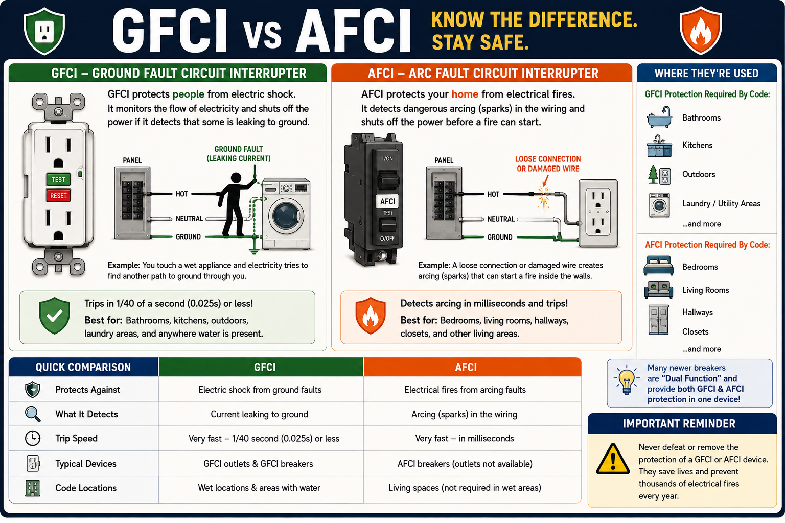
GFCI Protection
A GFCI, or ground-fault circuit interrupter, is designed to respond quickly to certain differences between current leaving and returning through the intended circuit conductors.
If some of that current is escaping through an unintended path, the device can disconnect the circuit rapidly under qualifying conditions.
GFCI protection is strongly associated with areas where electricity, people, water and grounded surfaces may come together. Bathrooms, kitchens, outdoor locations and similar areas are familiar examples, although the actual requirements depend on the electrical code that governs the project.
GFCI protection may be provided by a receptacle, breaker or other approved device depending on the installation.
One important distinction is that an ordinary circuit breaker and a GFCI do not perform exactly the same function. A circuit having overcurrent protection does not automatically mean it has ground-fault protection.
AFCI Protection
An AFCI, or arc-fault circuit interrupter, addresses another electrical hazard: dangerous electrical arcing.
Arcing can result from damaged conductors, deteriorated insulation, loose connections or other faults. The electrical characteristics of certain dangerous arcs may not look identical to a conventional overload.
Arc-fault protective devices are designed to identify characteristics associated with dangerous arcing and interrupt the circuit when appropriate.
Modern electrical codes have expanded arc-fault requirements considerably compared with many older installations. That is why somebody comparing a modern electrical panel with one installed decades ago may notice very different breakers and protective equipment.
A new tiny house should be designed according to the electrical code currently applicable to the project, not by copying whatever happened to be installed in an old house.
Grounding and Bonding: The Part People Commonly Get Wrong
Grounding and bonding are two terms that get thrown around constantly in electrical discussions. They are related but not identical.
Bonding generally involves intentionally connecting conductive parts together so they remain electrically connected and provide an effective path for fault current. Grounding involves connecting designated parts of the electrical system to ground according to the system design and applicable code.
Why does this matter? Because metal electrical boxes, equipment enclosures and other conductive components should not become dangerous shock hazards if an energized conductor accidentally contacts them.
A properly designed fault path allows substantial fault current to flow so protective equipment can clear the fault. A weak or incorrect fault path can leave energized metal sitting at a dangerous voltage.
The subject gets more complicated when you reach service equipment, grounding electrodes, downstream panels, generators, inverters and separately derived systems. That complexity is another reason electrical panel installation should never be treated as “just connect the wires to the bars that look right.”
Planning the Electrical System for a Tiny House
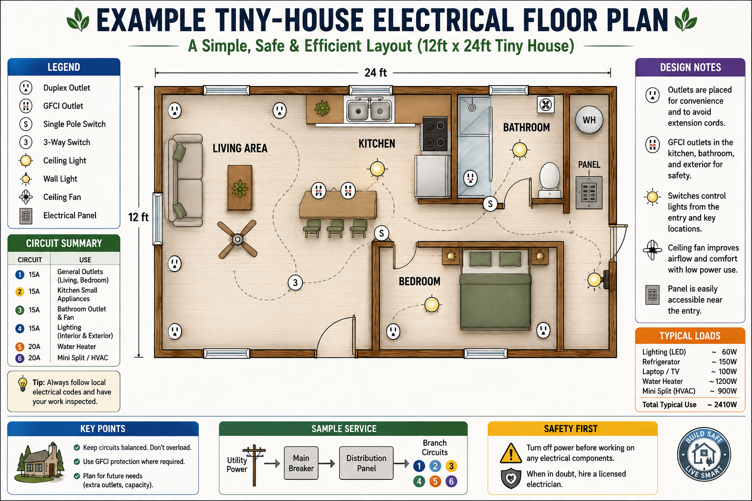
Before running a single cable, create an electrical floor plan. Start with the actual layout of the house rather than thinking about breakers.
Where will the refrigerator sit? Where will the bed be? Where are the kitchen counters? Where will somebody plug in a laptop beside the couch? Where are the bathroom mirror, exterior door, water heater, heat pump and major appliances?
Once you know how the house will function, mark the desired locations for receptacles, switches, lighting fixtures and permanently connected equipment. Then collect the electrical specifications for significant appliances and mechanical systems.
A useful planning checklist should include:
- Interior lighting
- Exterior lighting
- General receptacles
- Kitchen receptacles
- Bathroom receptacles
- Refrigerator
- Microwave
- Cooking equipment
- Range hood or exhaust fan
- Water heater
- Heating equipment
- Air-conditioning or heat-pump equipment
- Bathroom ventilation
- Smoke and carbon-monoxide alarms
- Exterior receptacles
- Washer or dryer if equipped
- Internet and low-voltage equipment
- Solar equipment if planned
- Battery storage if planned
- Generator connection if planned
- Future workshop, EV or outdoor loads
Once those loads are known, an electrical designer or qualified person can begin determining how they should be divided among circuits and how much electrical capacity the building requires.
This is far better than installing a small panel first and discovering halfway through the build that your appliance choices require considerably more electrical capacity than expected.
The Tiny-House Load Problem
Tiny-house design creates an interesting contradiction. The house itself is small, but the appliances are not necessarily proportionally small.
Ten LED light fixtures may consume very little electricity. The refrigerator is manageable. Then you add an electric water heater, induction cooktop, microwave, toaster, coffee maker, clothes dryer and heating system.
Suddenly the tiny house can have a very large electrical appetite.
This is particularly important for off-grid designs. People sometimes assume that covering a tiny-house roof with solar panels will automatically provide enough energy to operate an all-electric lifestyle.
The reality depends on solar generation, battery capacity, inverter output, climate, heating demand, appliance efficiency and how much electricity is used throughout the day.
Electrical planning therefore overlaps with energy planning. Sometimes the most effective solution is not installing larger electrical equipment but choosing more efficient appliances or changing how certain loads are supplied.
Tiny House on a Foundation vs. Tiny House on Wheels
One of the biggest problems with generic “tiny house wiring diagrams” is that they often ignore how the structure is classified.
A small permanent dwelling on a foundation may fall under conventional residential electrical rules. A movable tiny house designed to connect to external power may fall under different requirements or standards.
A tiny house that looks identical in an Instagram photograph may therefore require a very different electrical system depending on whether it is legally a house, accessory dwelling, recreational vehicle or another type of structure.
This can affect supply connections, grounding and bonding, disconnecting means, wiring methods, equipment approvals and inspections.
Before purchasing an electrical panel or designing the power inlet, determine how the structure will legally be classified where it is built and used.
That may not be the glamorous part of tiny-house construction, but finding out before the walls are built is dramatically easier than finding out afterward.
Shore Power
Some movable tiny homes receive electricity through what is generally described as shore power. Instead of having a conventional utility service permanently attached to the structure, the building connects to an external power source.
This arrangement may look superficially similar to plugging in an enormous extension cord, but the electrical design is considerably more involved. Supply capacity, connector ratings, cable sizing, overcurrent protection, grounding, bonding and disconnect requirements all matter.
The available shore-power capacity also creates a hard ceiling on how much electricity can be used simultaneously. An all-electric tiny home with significant heating and cooking loads may require considerably more capacity than somebody initially expects.
That is another reason appliance planning should happen early.
Solar Panels, Batteries and Inverters
Tiny houses and solar power naturally seem made for each other. A small structure requires less energy than a large house in many respects, and a rooftop solar array can contribute meaningfully to the building’s energy needs.
But adding solar does not make the electrical system simpler. It creates another electrical system that must integrate safely with the building.
A solar-and-battery setup may contain photovoltaic modules, DC conductors, charge controllers, disconnects, overcurrent protection, battery banks, inverters and AC distribution equipment. Hybrid systems may also interact with utility power or generators.
Battery systems deserve particular respect because they can store enormous amounts of energy. Disconnecting utility power does not necessarily mean the electrical system is dead when batteries, generators or photovoltaic sources remain connected.
If you are just beginning to learn residential wiring, it makes sense to understand ordinary branch circuits first. Solar generation and battery storage can then be studied as additional systems rather than treating “off-grid” as synonymous with “simple.”
What Tools Do Electricians Use?
Electrical work involves specialized tools, but buying the tools is the easy part. Knowing how and when to use them is what matters.
Common electrical tools can include wire strippers, cable cutters, lineman’s pliers, appropriately rated screwdrivers, torque tools, multimeters, voltage testers, fish tapes, cable-pulling tools and circuit tracers. Different installations may require considerably more specialized test equipment.
A multimeter is particularly useful, but it can also be dangerous when used incorrectly. You need to understand what measurement you are attempting, where the probes should be placed, what meter setting is appropriate and what result you should expect.
Non-contact voltage testers can also be useful tools, but they should not become a replacement for proper testing procedures and circuit understanding.
One of the more overlooked ideas in DIY electrical work is torque. Electrical terminals are engineered connections. Manufacturers may specify how connections are made and how tightly terminals must be secured.
“Really tight” is not an electrical specification.
Why Good Electrical Work Looks Boring
There is a funny pattern you start noticing when you learn more about construction. Amateur work often tries to look clever, while professional work often looks almost boring.
Good electrical work generally consists of approved components installed in predictable ways. Boxes are properly sized. Cables are properly supported and protected. Conductors are terminated correctly. Connectors are appropriate for the wires they join.
Circuits are labeled. Work remains accessible where required. Equipment instructions are followed instead of improvised around.
There is very little value in inventing a creative electrical shortcut.
In woodworking, creativity can produce something beautiful. In residential electrical wiring, creativity is best used during planning. The actual installation should generally be disciplined and predictable.
Common Beginner Assumptions That Can Get You Into Trouble
Electrical systems become easier to understand once you get rid of a few assumptions that sound logical but can be dangerously wrong.
- “The breaker is off, so everything inside the box must be dead.”
- “The main breaker is off, so nothing inside the panel can be energized.”
- “White always means neutral.”
- “Ground and neutral are basically the same thing.”
- “If the breaker keeps tripping, I need a larger breaker.”
- “If the wire fits inside the connector, the connector must be correct.”
- “Any indoor cable can be used outdoors if I protect it.”
- “A tiny house only needs a tiny electrical supply.”
- “If the circuit works, it must have been wired correctly.”
- “A YouTube wiring diagram must be acceptable where I live.”
- “Electrical codes are mostly bureaucratic rules.”
- “I can learn the panel installation part as I go.”
That last assumption is particularly dangerous. There is an enormous difference between understanding what a breaker panel does and safely performing work around energized service conductors.
The more electrical knowledge you gain, the clearer that boundary becomes.
Can You Wire Your Own House?
There is no universal answer because electrical regulations vary by jurisdiction.
Some locations allow homeowners to perform certain electrical work on property they own, provided the required notifications, permits or inspections are obtained. Other types of work may require licensed electrical contractors.
Ontario provides a useful example. The Electrical Safety Authority states that homeowners performing DIY electrical work in their own homes must file a notification of work with ESA, and installations must be reviewed as required before work is concealed. The 2024 Ontario Electrical Safety Code, 29th Edition, became effective May 1, 2025.
Those rules should not be assumed to apply in another province, state or country. Before doing electrical work, contact the authority responsible for electrical safety where the project is located.
For Ontario homeowners, ESA’s DIY electrical-work guidance is an excellent starting point. ESA DIY Electrical Work Guide
Readers who want to understand the current Ontario electrical-code framework can also review ESA’s information on the Ontario Electrical Safety Code. Ontario Electrical Safety Code Information
Electrical Inspections Are Not the Enemy
DIY builders sometimes look at permits and inspections as bureaucratic obstacles standing between them and finishing a project. Electrical work is one area where that attitude deserves reconsideration.
Many electrical problems disappear behind drywall, ceilings and finished surfaces. Once the house is completed, checking those hidden installations becomes considerably more difficult.
An inspection gives another qualified set of eyes an opportunity to identify problems while they can still be corrected.
In Ontario, ESA specifically notes that electrical installations must be inspected at appropriate milestones and should not be concealed before the required review.
For somebody learning electrical work, having a legal inspection process is not merely an obligation. It is an additional layer of protection.
What Should You Know Before Attempting Electrical Work?
If you want to eventually perform legal homeowner electrical work yourself, being able to recognize black, white and green wires is only the beginning.
You should understand basic electrical theory, circuit protection, conductor sizing, grounding and bonding, wiring methods, boxes, device ratings, load calculations and safe testing procedures.
You should also be comfortable reading diagrams and manufacturers’ instructions rather than copying installations from photographs.
Most importantly, you need to recognize when a particular task exceeds your knowledge. There is nothing inconsistent about wiring some legally permitted branch circuits yourself while hiring a licensed electrician for service or panel work.
In fact, recognizing that boundary is evidence that you are learning.
Why Learn All This If You Are Going to Hire an Electrician Anyway?
Because understanding your electrical system still makes you a better homeowner and a better DIY builder.
You will be able to plan renovations more intelligently. You can communicate with electricians using the correct terminology. You will better understand why installing a new appliance might require another circuit or additional electrical capacity.
You will also become better at recognizing suspicious work. An unlabeled panel, open junction box, damaged cable or obviously improvised connection is much easier to question when you understand what properly planned electrical work is supposed to accomplish.
Tiny-house builders benefit even more because so many design decisions affect the electrical system. Choosing between electric and gas cooking changes the load. Choosing a resistance heater versus a heat pump changes energy demand. Selecting an electric water heater can dramatically affect the available electrical capacity.
Electrical literacy gives you the ability to make those decisions before construction rather than discovering the consequences afterward.
The Most Important Thing to Understand About DIY Electrical Work
Electricity rewards methodical thinking and punishes guesswork.
A poorly cut piece of lumber is visible immediately. A crooked tile looks bad as soon as it is installed. A plumbing leak often announces itself by putting water somewhere it should not be.
Electrical mistakes can be different. A connection may appear to work perfectly while developing excessive resistance. An incorrect grounding arrangement may remain unnoticed until a fault occurs. A damaged conductor can stay hidden inside a wall for years.
That delayed nature of electrical failure is one reason “it works” is such a poor standard for determining whether electrical work is safe.
Correct electrical work needs to operate properly and remain safe when something eventually goes wrong.
Final Verdict: Residential Wiring Is Logical, but It Is Not Casual DIY
Once you begin learning the basics, residential wiring becomes surprisingly logical. Voltage provides the electrical potential, current flows through circuits, loads consume power, breakers provide overcurrent protection, conductors carry current, grounding and bonding help manage faults, and the panel distributes electricity throughout the building.
The mystery starts disappearing.
That does not mean the danger disappears with it.
A few hours of reading may help you understand why a black conductor goes to one terminal and a white conductor goes to another. It does not automatically teach you how to assess an existing installation, perform a load calculation, select every component correctly, establish grounding and bonding, safely test circuits or work near energized electrical equipment.
And that is perfectly fine.
The first goal should not be to wire an entire tiny house tomorrow. The first goal should be to look at an electrical system and understand what you are seeing.
Learn what volts, amps and watts mean. Understand hot, neutral and ground. Learn why wire gauge matters. Understand what breakers actually protect. Learn why the colored wire connector must be sized for the conductors rather than chosen because its color looks right.
Then learn how branch circuits, panels, grounding, GFCI protection, AFCI protection and load planning fit together.
At that point, you can make an informed decision about which work you are qualified and legally permitted to perform yourself and which parts should be handed to a licensed electrical professional.
That knowledge is useful whether you wire one receptacle or never touch a conductor in your life.
And the next time you look inside an electrical box and see black wires, white wires, bare copper and a handful of red, yellow and blue connectors, it will no longer look like a mysterious collection of parts.
You will see a system.
The important part is knowing enough to understand the system without confusing understanding with permission to take unnecessary risks.